英文原版 https://maniacbug.wordpress.com/2012/03/30/rf24network/
翻译: Vincent Mi http://vnzmi.com/rf24network-for-wireless-sensor-networking.html
RF24Network网络是一个使用Nordic nRF24L01+ 无线,运行在Arduino兼容硬件的网络层。他的目标是成为Arduino单元通信的除Xbee外的另外一个选择。他提供一个主机地址空间和消息路由最高支持6000个节点,形成一个有能力和可扩展的无线传感器网络系统。 同时让两个节点之间的通讯更加简单。
今天,我在一个单独的网络管理17个节点。现在我需要创建更多的节点,因为这个系统可以很好的工作在17个节点,也可以处理上千的节点。
硬件
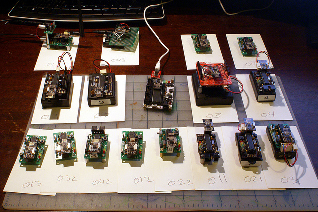
Arduino ,最快的获取RF24兼容硬件的方式是创建一个入门板,或者ProtoShield板。这些可以从其他的一些文章找到。如下图中 03 和043。 .
最后我需要一些更小,更便宜,更节能,所以我创建了一个低能耗无线传感器节点。这篇文章内容使用了V3版本的传感器单元。见附图,他们是04,011,021,而01,02使用的是更早的版本。其余的使用更高的版本。创建的他们的方式都略有不同。这带给我大量经验去找到更好的打包方式。最后031节点获得了优胜。将作为V5版本进行迭代优化。我将创建10个使用2个AA电池安装PCB板的节点。
简单的发送和接收
这个Hello World示例说明在两个节点通讯有多简单。接收在一个节点发送在另外的节点。
这里有三个部分:
静态初始化
首先,静态初始化准备这个无线电,设置地址。在这个例子,我们认为我们自己是 “Node #1” ,将与 “Node #0” 进行通讯。当然跳线要结对。在这个例子中我们使用9和10.
// nRF24L01(+) radio attached using Getting Started board
RF24 radio(9,10);

// Network uses that radio
RF24Network network(radio);

// Address of our node
const uint16_t this_node = 1;

// Address of the other node
const uint16_t other_node = 0;

// How often to send 'hello world to the other unit
const unsigned long interval = 2000; //ms

// When did we last send?
unsigned long last_sent;

// How many have we sent already
unsigned long packets_sent;

// Structure of our payload
struct payload_t
{
  unsigned long ms;
  unsigned long counter;
};
setup()
第二步, ‘setup()’ 简单的打印出一个欢迎信息并初始化无线层。
void setup(void)
{
  Serial.begin(57600);
  Serial.println("RF24Network/examples/helloworld_tx/");

  SPI.begin();
  radio.begin();
  network.begin(/*channel*/ 90, /*node address*/ this_node);
}
发送 loop()
最后, loop()通常发送消息到其他单元。 记住RF24Network通常需要调用update() 来处理数据包。最好不要调用delay在整个系统中。
void loop(void)
{
  // Pump the network regularly
  network.update();

  // If it's time to send a message, send it!
  unsigned long now = millis();
  if ( now - last_sent >= interval  )
  {
    last_sent = now;

    Serial.print("Sending...");
    payload_t payload = { millis(), packets_sent++ };
    RF24NetworkHeader header(/*to node*/ other_node);
    bool ok = network.write(header,&payload,sizeof(payload));
    if (ok)
      Serial.println("ok.");
    else
      Serial.println("failed.");
  }
}
接收 loop()
还有我们来看一下接收器的例子,这个和传输的loop()有所不同。他一直查询数据包从无线模块取出,打印到控制台。
void loop(void)
{
  // Pump the network regularly
  network.update();

  // Is there anything ready for us?
  while ( network.available() )
  {
    // If so, grab it and print it out
    RF24NetworkHeader header;
    payload_t payload;
    network.read(header,&payload,sizeof(payload));
    Serial.print("Received packet #");
    Serial.print(payload.counter);
    Serial.print(" at ");
    Serial.println(payload.ms);
  }
}
地址分布
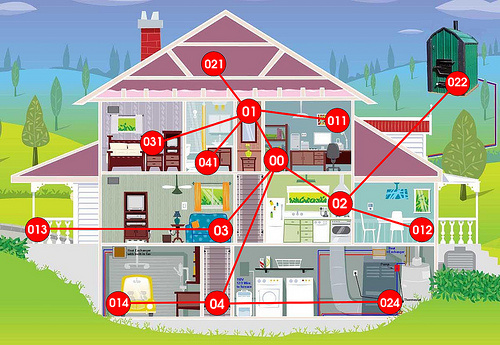
RF24Network在节点少的时候工作的非常好,但是他是设计用于整个房间的节点。节点在树拓扑中根据节点地址自动配置。节点只能直接与他们的父节点和子节点进行通信。网络将自动发送消息到正确的地方。
#00是 基础节点,#01-#05 直接与#00通讯,但是互相之间不进行通讯。所以如果#01要发送消息到#02,他将通过#00的转发,#011,#021,#031等等是#01的子节点。所以#011发送到#02,他将发送到 #01然后#00 然后#02.因此,如果你放一个节点#011到你的网络,确定有节点#01在网络,并且是开启电源也在通讯范围内。
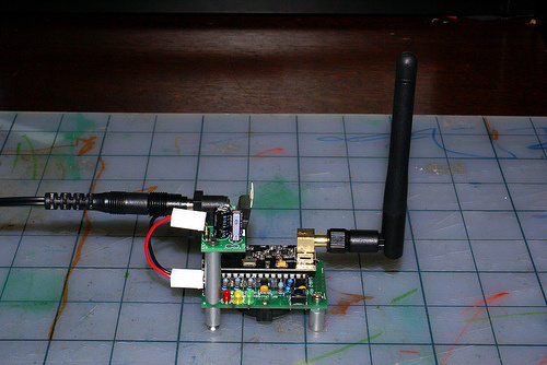
在实践中,我设计了router(路由)节点 #01-#05到每一层,使用了外接天线和墙壁电源。然后本层的所有节点都与本层的父节点进行通讯。上面的图片是一个标准的V3节点,加上特别的电源模块。以便可以插入墙壁电源。无线单元被加上了天线。
创建无线传感器网络
sensornet(传感器网络)的例子是开始创建传感器网络的地方。这个例子演示如何从任意节点发送一对传感器读数到根节点。 读数是一个连接到模拟输入A2的温度传感器,以及一个电压传感器连接到A3口。每个节点没4秒会发送ping到基本节点。这个一个很好的心跳检测。在实际的系统中你将可能需要更长的时间间隔。叶子节点将休眠以延迟电池寿命。
根节点简单的转储到控制台并跟踪数据包的丢失情况。这样我们可以在测试时检查网络的健康状况。在真实的应用中。你可能需要存储或者发送这些内容到其他地方。比如 Pachube(Vincent:一个云平台,收集传感器信息);
载荷详情
RF24网络在每一帧中发送2部分的内容,头和内容。头由库文件定义用来确保帧被发送到正确的地方和提供标准信息。定义在RF24Network.h 中.
/**
* Header which is sent with each message
*
* The frame put over the air consists of this header and a message
*/
struct RF24NetworkHeader
{
  uint16_t from_node; /**< Logical address where the message was generated */
  uint16_t to_node; /**< Logical address where the message is going */
  uint16_t id; /**< Sequential message ID, incremented every message */
  unsigned char type; /**< Type of the packet.  0-127 are user-defined types, 128-255 are reserved for system */
  unsigned char reserved; /**< Reserved for future use */

...
这个消息是由应用定义,页头使用一个单独的字符来跟踪消息的类型。这样你的应用可以有不同的消息类型来传输不同类型的信息。在这个sersornet示例中,我们将只使用类型为S的消息。意思是 “Sensor Data”.
消息的定义在头文件S_message.h:
/**
* Sensor message (type 'S')
*/

struct S_message
{
  uint16_t temp_reading;
  uint16_t voltage_reading;
  S_message(void): temp_reading(0), voltage_reading(0), counter(next_counter++) {}
  char* toString(void);
};
这个简单的包含了一个温度和电压读数。这个值是8.8位值,高位是数字低位是小数。例如 3.5V则为0x380.还包含一个方法转换成字符串用于输出。
电压传感器
我喜欢监控每个节点的电池的级别,这样我可以知道是否一个节点什么时候需要更换电池。因此我连接来自我们电池的正级到电压传感器的输入。通过一个分压器:
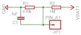
我使用一个1M/479K 分频器电路。他将3.44V电压降低到1.1V,然后使用这个1.1V的电压做参考。这对于我的使用很完美,因为我不会使用超过3.44V的电压。当然如果你的电压超过了,你将需要一个大点的分压器。在我的这个示例中,当analogRead(A3)返回1024,我的电压是3.44V.代码如下:
// What voltage is a reading of 1023?
const unsigned voltage_reference = 5 * 256; // 5.0V
// How many measurements to take.  64*1024 = 65536, so 64 is the max we can fit in a uint16_t.
const int num_measurements = 64;
...
    // Take the voltage reading
    i = num_measurements;
    reading = 0;
    while(i--)
      reading += analogRead(voltage_pin);

    // Convert the voltage reading to volts*256
    message.voltage_reading = ( reading * voltage_reference ) >> 16;
首先,我获取64个读数,去得到一个良好的的样本大小,对于64个读数另外一个优势是这样的,他使用16bit的uint16_t,所以一个值0x8000是最大值1.1V的一半。下面我与电压参考相乘。这个参考认为. First, I take 64 readings, to get a good sample size. The other advantage to 64 readings is that it uses the full 16-bits of a uint16_t, so a value of 0x8000 is half of the max 1.1V. Next, I multiply it by the voltage reference. That reference considers the voltage divider I have in place, telling me what voltage I ‘really‘ have on the battery if I get an 0xFFFF reading. In the case of the example, it’s 0x500, or 5V. Finally, I shift it down so the decimal point is in the correct place for an 8.8 fixed point value.
温度传感器
在这个例子中,我选择MCP9700作为我的温度传感器。你可以选择任何你喜欢的传感器,只是记得调整计算公式。MCP9700工作时产生0.5V的电压在0度。每增加1度电压增加0.01V。完美的1.1V内部模拟参考。下面是在示例中的使用:
   // Take the temp reading
    i = num_measurements;
    uint32_t reading = 0;
    while(i--)
      reading += analogRead(temp_pin);

    // Convert the voltage reading to celsius*256
    // This is the formula for MCP9700.
    // V = reading * 1.1
    // C = ( V - 1/2 ) * 100
     message.temp_reading = ( ( ( reading * 0x120 ) - 0x800000 ) * 0x64 ) >> 16;
和上面一样,我首先采样64此以获取0x0000 到 0xFFFF的值。然后使用以下的步骤进行转换:
- 乘以0x120将 1.1进行8.8的小数点修正. 读入伏数并且增加增加8位小数位。
- 减 0x800000,也就是 0.5, 因为小数位超出了24bit.
- 乘 0x64 也就是 100
- 右移16位,将小数点从24bit移到我们需要的8bit.
所有这些工作是在一个32位的整数,以便有充足的位来执行此计算。
部署
将代码上传到每个节点,开始他首选连接到串口,你可以给它设置一个地址:
RF24network/examples/sensornet/
PLATFORM: Getting Started Board
VERSION: 013b4d3
*** No valid address found. Send node address via serial of the form 011<cr>

1733003: APP Received #16 24.23C / 3.21V from 053
1733709: APP Received #37 23.82C / 2.70V from 043
1734297: APP Received #109 24.46C / 3.06V from 013
1735108: APP Received #55 25.16C / 3.06V from 033
1735224: APP Received #134 22.66C / 2.71V from 031
1735286: APP Received #287 25.10C / 3.24V from 01
1735565: APP Received #299 24.79C / 3.36V from 03
1736871: APP Received #71 25.78C / 3.07V from 023
1737094: APP Received #137 22.89C / 3.01V from 041
1737119: APP Received #120 23.69C / 2.98V from 011
1737247: APP Received #17 24.23C / 3.21V from 053
1738025: APP Received #38 23.82C / 2.70V from 043
1738361: APP Received #110 24.45C / 3.06V from 013
1739286: APP Received #288 25.11C / 3.24V from 01
1739404: APP Received #56 25.16C / 3.06V from 033
1739565: APP Received #300 24.78C / 3.36V from 03
1739574: APP Received #135 22.68C / 2.71V from 031
1741043: APP Received #72 25.77C / 3.07V from 023
1741213: APP Received #138 22.87C / 3.01V from 041
1741490: APP Received #121 23.68C / 2.98V from 011
1741492: APP Received #18 24.21C / 3.21V from 053
设置休眠时间间隔
一旦他启动并且运行。你可以修改为更适合正式网络的休眠时间。我设置为每分钟从节点读取一次读数,这个可能不合适,但是可以提供一更多的扩展性。业务有时候当多个节点数据同一时间抵达跟节点时会有一些麻烦,这是一些调整的值:
// Sleep constants.  In this example, the watchdog timer wakes up
// every 4s, and every single wakeup we power up the radio and send
// a reading.  In real use, these numbers which be much higher.
// Try wdt_8s and 7 cycles for one reading per minute.> 1
const wdt_prescalar_e wdt_prescalar = wdt_4s;
const int sleep_cycles_per_transmission = 1;
接下来的步骤
这个传感器网络实例可以设置大量的传感器节点让他们启动和运行。但是之后你将如何使用这些数据?或许你像传输或者存储到某些地方,这个将会是下一篇介绍的内容。
提交到Pachube
和NanoDeVIP合并,我们可以从数以千计的传感器提交读数到Pachube.(或者至少从17个开始:))。
使用PC程序来监控网络
串口包含包含了比较多的节点信息。我正在开发一个C# WPF应用程序去总揽一个网络查看网络的工作情况。这非常不错,完成后我会分享给大家。
个人的简化版Pachube.
Pachube是一个非常棒的东西,但是有几次我可能需要自己调整扑捉我数据库的读数。他回比Pachube做的少 但是我们对我的读数数据库进行我想做的任何操作。我写好了我自己的PHP+MySQL方案,但是不太好移植。我最新的想法是用Ruby on Rail服务器来实现他,ROR看起来很适合做这个。
附件作者的源代码 sensornet.zip
RF24 Git Repo RF24 Network Repo
VCC  -|       |-VCC
CE   -|       |-CSN
SCK  -|       |-MOSI
MISO -|       |-IRQ
GND  -|       |-GND

Line	Arduino
GND	        GND
3V3	        3V3
CE	         9
CSN	        10
SCK	        13
MOSI	11
MISO	12
「真诚赞赏,手留余香」
 我的乐与怒
我的乐与怒
真诚赞赏,手留余香
使用微信扫描二维码完成支付